Particle shape and shape descriptors
The primary measuring information of image analysis methods is the projected area of a particle. This makes a difference to the laser diffraction and the ultrasonic extinction, because from the projected area additional information can be determined about the shape of the particles, though two-dimensional only, represented as the contour of the area.
The arbitrary formed projected area of a particle can be expressed by miscellaneous data, which always expresses the particle size. This data may consist of diameter or length values, that are generally called diameter in this context. A wide number of algorithms have been published to calculate these diameters, the most important of which are available in the DIA evaluation software. Other parameters named as shape parameters or shape descriptors serve to the compact description of the particle shape. The available diameters and shape descriptors can be selected in the evaluation settings.
The description of fibres is a relatively young and strongly developing field of image analysis. Consequently, the definitions of size and shape parameters are not at all standardized, nor are the algorithms for their calculation. PAQXOS features a calculation for the length and the diameter of a fibre and the straightness for its shape.
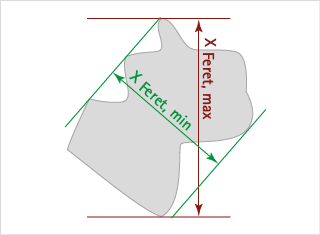
This is not a diameter in its actual sense but the common basis of a group of diameters derived from the distance of two tangents to the contour of the particle in a well-defined orientation. In simpler words, the method corresponds to the measurement by a slide gauge (slide gauge principle). In general it is defined as the distance between two parallel tangents of the particle at an arbitrary angle. In practice the Minimum xFmin and Maximum Feret Diameter xFmax>, the Mean Feret Diameter and the Feret Diameters obtained at 90° to direction of the Minimum and Maximum Feret Diameters xFmax90 are used. The minimum Feret diameter is often used as the diameter equivalent to a sieve analysis.
Maximum Feret diameter | FERETmax
The Feret diameters for a sufficient number of angles are calculated, and their maximum is selected. If a particle has an irregular shape, the Feret diameter varies more than with regularly shaped particles. The maximum Feret diameter is always larger, than the diameter of the equivalent circle (EQPC).
Minimum Feret diameter | FERETmin
The Feret diameters for a sufficient number of angles are calculated, and their minimum is selected. If a particle has an irregular shape, the Feret diameter varies more than with regularly shaped particles. The minimum Feret diameter is always smaller, than the diameter of the equivalent circle (EQPC).
Mean value of the Feret diameters over all orientations according to the principle before.
First, the maximum Feret diameter, FERETmax, is calculated. The result is the Feret diameter measured at an angle of 90 degrees to that of the maximum Feret diameter.
First, the minimum Feret diameter, FERETmin, is calculated. The result is the Feret diameter measured at an angle of 90 degrees to that of the minimum Feret diameter.
The cylindrical Feret volume diameter, FERETvol, represents a diameter of a sphere having the same volume as the cylinder constructed by FERETmin as the cylinder diameter and FERETmax as its length.
The calculation of the minimum bounding rectangle area is based on the product of each pairing of a Feret diameter FERET and its corresponding diameter in perpendicular direction FERET90. The length of that rectangle is returned as BRmax and its width as BRmin.
Minimum Area Bounding Rectangle, Length / BRmax
The larger dimension of the bounding rectangle with the smallest area is output.
Minimum Area Bounding Rectangle, Width / BRmin
The smaller dimension of the bounding rectangle with the smallest area is output. This dimension corresponds quite well to the results of a sieve analysis.
A chord length is defined by the straight distance of two points of the particle contour. The calculation is done in two steps and results in two chord length values:
The image of a particle is turned by 180 degrees in steps of 9 degrees. For each rotation the maximum horizontal chord is determined. The following image shows a sketch for six of the resulting orientations of a particle, including the maximum horizontal chord for each orientation.

Now the longest maximum chord CHORDmax and the shortest maximum chord CHORDmin from all orientations give the respective results.
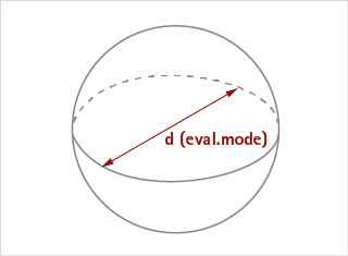
Sphere volume from current calculation mode
This volume model uses the currently selected calculation diameters.
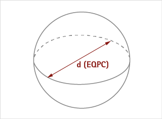
Sphere volume from EQPC
This volume model uses the EQPC diameter independent from the currently selected calculation diameter.
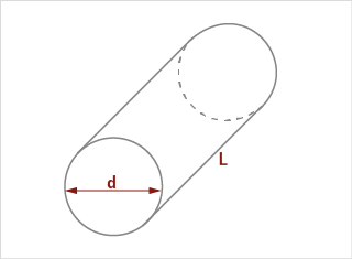
Cylinder volume
Two kind of cylinder volume models
A) FERET cylinder
d = FERETmin | L = FERETmax
B) Fiber length cylinder
d = DIFI | L = LEFI
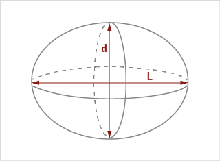
Ellipsoid volume
Two kind of ellipsoid volume models
A) FERET ellipsoid
d = FERETmin | L = FERETmax
B) CHORD ellipsoid
d = CHORDmin | L = CHORDmax
Aspect ratio
The ratio of the minimum to the maximum Feret diameter is another measure for the particle shape. The Aspect Ratio ψA (0 < ψA≤ 1) is defined by the ratio of the Minimum to the Maximum Feret Diameter ψA = xFeret min / xFeret max. It gives an indication for the elongation of the particle. Some literature also used 1/ψA as the definition of sphericity.
Sphericity
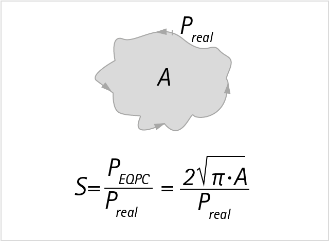
The sphericity S is the ratio of the perimeter of the equivalent circle, PEQPC, to the real perimeter, Preal. The result is a value between 0 and 1. The smaller the value, the more irregular is the shape of the particle. This results from the fact that an irregular shape causes an increase of the perimeter. The ratio is always based on the perimeter of the equivalent circle because this is the smallest possible perimeter with a given projection area.
Elongation
Convexity
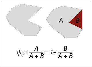
The convexity is an important shape parameter describing the compactness of a particle. The figure below shows a particle with projection area A (grey/light) leaving open a concave region of area B (red/dark) on its right hand side. The convexity is the ratio of the projection area itself (A) and the area of the convex hull (A+B). The maximum theoretical convexity is 1, if there are no concave regions. Due to the detector design of a digital camera (square pixels), however, all particles seem to have small concave regions, corresponding to the tiny steps with every pixel in the perimeter line. Therefore, the maximum convexity calculated in reality is mostly limited to 0.99.
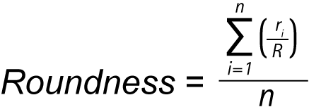
Roundness
Straightness of fibre shaped particles
Most fibres, especially longer ones, tend to curl, and there have been several efforts to describe this phenomenon in terms of a single parameter. One of the possible definitions is the straightness (according to ISO standard 9276-6):
STRAIGHTNESS = FERETmax / LEFI
The definitions of LEFI, the fibre length, and FERETmax, the "slide gauge compliant" outer dimension of the fibre, can be found above in this text. A value of 1 of the straightness represents a perfectly straight particle while values close to zero represent a greater deformation (curled fibres). An older definition of straightness is the Curl Index:
CURLindex = LEFI / FERETmax - 1
which reflected the tradition in some industries, mainly the wood processing industry.
A fibre shaped particle is characterised by a length that is typically much larger than its diameter and an irregular shape. Consequently both, length and diameter, are necessary to properly describe the size of a fibre. The above definition of a fibre is imprecise but there is no better one, nor is there a standardised criterion which shape of a particle projection is considered as "fibre-shaped" and which is not. The evaluation methods described below can therefore be applied to particles of any shape if desired. It is then up to the user to judge the usefulness of the evaluated results.
Length of fibre / LEFI
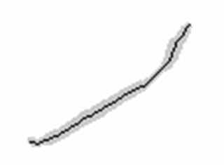
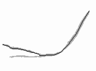
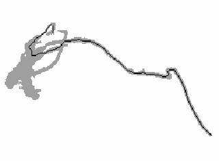
The length of a fibre is defined as the direct connection between its opposite ends, this is the longest direct path from one end to another within the particle contour. Direct means without loops or deviations. The crucial technique used to calculate this value is called "skeletonizing", it means to reduce the dimensions of the fibre from all directions until one or more lines of one pixel width remain. The black line in the fibre images represent the longest direct path along their skeleton. Its length is the result of the LEFI calculation.
A very simple contour of a fibre is shown in image 1. It is simple because it has no branches or nooses, and its length-to-diameter ratio is large. Its opposite ends can clearly be defined, and there is not much discussion about what should be their connecting path.
Matters get a bit more complicated for image 2. The algorithm for the identification of the opposite ends has to try two branches and select the longer one.
Image 3 shows a complex fibre with branches and nooses. The effect of the skeletonizing algorithm can clearly be seen in this picture. The clue of the path finding algorithm is to avoid loops.
Diameter of fibre / DIFI and DIFIX
There are severals ways to describe the diameter of a fibre by an average value. The method implemented in PAQXOS is to divide the projection area by the sum of all lengths of the branches of the fibre skeleton.
The calculation of DIFI is applied to those fibres only that are completely within the image frame, whereas the calculation of DIFIX also includes fibres touching the edge of the image.
Volume based fibre diameter / VBFD
This diameter is defined as the diameter of a sphere which has the same volume as the respective fibre. It is calculated with xD, the fibre diameter (DIFI) and xL, the fibre length (LEFI). The volume based fibre diameter is very useful if sample material consists of a mixture of granulate and fibres, and a distribution diagram of volume over particle size is desired. Neither LEFI nor DIFI can be used appropriately for the x-axis of a volume distribution diagram but VBFD serves to an informative representation.


